ЖИ көмекші


жүктеу мүмкіндігіне ие боласыз
Бұл материал сайт қолданушысы жариялаған. Материалдың ішінде жазылған барлық ақпаратқа жауапкершілікті жариялаған қолданушы жауап береді. Ұстаз тілегі тек ақпаратты таратуға қолдау көрсетеді. Егер материал сіздің авторлық құқығыңызды бұзған болса немесе басқа да себептермен сайттан өшіру керек деп ойласаңыз осында жазыңыз
 09 Наурыз 2025
 201
201
Химия пәнінен лабораториялық жұмыс
LABORATORY WORK # I
PREPARATION OF CAUSTIC SODA BY ELECTROCHEMICAL METHOD
1. Purpose of the work:
-
With the technology of producing caustic soda by electrochemical method
acquaintances. Study of the main electrode processes in the electrolysis of sodium chloride solution.
2) Determination of technological parameters of the process: electrolysis
calculation of output by current and the degree of application of electric energy.
-
Parameters of electrolysis (duration of the process,
determination of the influence of concentration, current strength) on the main process parameters.
description of the installation and working procedure
3.1 installations, technical and instrumental means:
1. electrolysis unit with diaphragm
2. chemical cookware
3. Titration setting
4. Liston A 1210 aquadistillators
3.2 installation description
A schematic version of the laboratory installation of a batch cell is shown in Fig. 1. 1.
The unit for electrolysis of an aqueous salt solution consists of an AC rectifier (18), a diaphragm cell (21), a rheostat (17), an ammeter (19) and a voltmeter (20). The cell consists of a box (4) and a cover (16). The conical bottom of the cell (10) is attached to the box and lid by means of a compression rod (5). Inside the cell there is a conductive ring (9), a lattice iron cathode (8), a horizontal asbestos diaphragm (7) and a rubber gasket (6). An Uruk (1), a horizontal disk (3) a carbon anode (2) and a glass tube (15)for feeding a saturated NaCl solution to the electrolyzer. Current is supplied to points (13) and (14) (cathode and anode current lines). The cell is placed on the supports (12), and a container (11) with the size for collecting the product is placed on the bottom of the cell (10).
An asbestos filter diaphragm is made by depositing an asbestos mixture on the cathode. To do this, 20-30g.of asbestos is crushed and boiled with the addition of water until a homogeneous mixture is formed within 15-20 minutes. The resulting mixture (using a Buchner urn and a Bunsen flask) is filtered using a vacuum pump onto the surface of a perforated iron cathode. To ensure the strength of the diaphragm, a filter cloth is placed on the surface of the iron cathode. The iron cathode together with the diaphragm is placed in a removable part of the cell, and the cylinder is bolted on top, placing the box and lid.
3.3 procedure for performing work
1. checks the correct assembly of the unit and the correct connection of measuring instruments.
2. a solution of sodium chloride of a given concentration is poured into the anode space so that the graphite disk is completely submerged, and the anode core is half submerged.
3. after connecting the unit to a current source, use the rheostat to set the applied current. Keeps the current value constant until the end of the experiment. Records voltmeter and ammeter readings.
4. under the given conditions, in order to ensure a constant position, electrolysis is carried out in the interval of 20 minutes, after which a 2-3-gigabyte analysis is carried out from the cathode space. For analysis, the sample is taken in the following order: put a 25 mm measuring cylinder on the bottom of the cell, start the stopwatch and collect the cathode liquid in an interval of 10 minutes. The cylinder is then replaced with another cylinder to produce a second sample.
5. measure the volume of the obtained catholyte and pour the cone into the flask. The inside of the cylinder should be thoroughly rinsed with distilled water and rinsed in a flask. If the volume of the initial sample is more than 10 ml, then 5 ml of it is taken for analysis using a pipette.
6. 2-3 drops of phenolphthalein are instilled into the solution in a cone flask as an indicator and titrated with a solution of 0.1 h HCl. If the indicator- is discolored by the ClO Ion, it is usually titrated by adding 2-3 ml of a 30% hydrogen peroxide solution to the solution.
7. according to the results of titration, the concentration of sodium hydroxide (g/l) Cin the catholyte withNaOH is calculated:
|
CNaOH= |
(1.24) |
|
where: V is the amount of 0.1 n HSI solution used for titration of the sample, ml;1 V1 is the volume of catholyte obtained for titration, ml; K is the correction factor of the 0.1 hsi solution; 0.004 is the NaOH content in 1 ml of 0.1 hsi solution. |
|

4 calculation of technological parameters of electrolysis
The main indicators of efficient use of energy in the electrolysis process are the current output and the degree of energy use.
-
The current consumption is calculated by the formula (1.6). For this
first, calculate the amount of substance obtained during electrolysis:
|
Gcorona= CNaOH V2/1000/1000 |
(1.25) |
|
where: V2is the volume of collected catholyte in a measuring cylinder, ml. |
|
The theoretical size of NaOH is calculated by formula (1.7). Then, the current output of caustic soda is calculated (formula(1.6)).
2. according to the formula (1.8), the degree of application of electric energy is calculated. To do this, first calculate the theoretical (wt) and experimental (Wt) energy costs using formulas (1.9) and (1.10), respectively.т) және тәжірибелік (WтәжIn this case, you can get the dependence expressed in terms of the current output:
|
= |
(1.26) |

3. All experimental data and calculation results are entered in Tables 1.1 and 1.2.
Table 1.1 -experimental data of the electrolysis process
|
Test № |
Test completion time (τ), min |
Current strength (?), A |
Kerneu U, in |
Volume of catholyte taken for titration V1, ml |
Volume obtained in 10 minutes (V2), ml |
0.1 h ni content per titration (V), ml |
|
|
U theoryтеор |
Ucrown |
||||||
|
|
|
|
|
|
|
||
Table 1.2-indicators of the electrolysis process
|
Primary solution concentration - %(withNaCl), % |
Test № |
NaOHNaOH Concentration Centers (S), g / l |
NaOH-ңAmount of NaOH, g |
Current output (), % |
Electric energy sources use degree (μ), % |
|
|
G theoryтеор |
Gcrown |
|||||
|
|
|
|
|
|
|
|
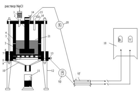
Figure 1.1 - installation of a batch cell. |
Based on the calculation results, the dependence of the process parameters on the electrolysis time and the NaOH composition in the catholyte is determined. In the course of conducting research, the influence of the concentration of a common salt solution on the amount of current consumption and the degree of use of electrical energy is studied and a conclusion is drawn on the effective technological rule of the electrolysis process.
LABORATORY WORK #2
CAUSTIFICATION OF SODA SOLUTION
1. Purpose of the work:
-
Introduction to the process of caustification of soda solution
-
Experimental and virtual study of the effect of process parameters on the degree of cauterization of soda solution.
-
Mastering the skills of performing laboratory work on a computer program in a virtual position.
description of the installation and working procedure
3.1. installations, technical and instrumental means:
1. laboratory installation for moxibustion
2. chemical cookware
3. Titration setting
4. Liston A 1210 aquadistillators
5. laboratory scales VLTE-150
6. vacuum filtration unit
3.4 procedure for performing work
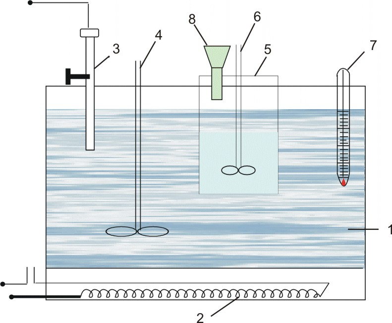
1. in a porcelain glass (5), pour the initial soda solution of a given amount (100-200 g) and place it in a thermostat (1), preheated to the desired temperature.
2. the mortar mixer is0heated to 80 0 C in the added causticizer, after which crushed lime stone is added to the solution within 5-10 minutes.
3. after adding all the lime stone designed for soda solution, set the start time of the experiment. Cautifications
Spends from 40 to 60 minutes. The moxibustion temperature should be constant 800C during the experiment.
4. At the end of the experiment, stop the mixer and remove the causticizer from the thermostat. To determine the degree of cauterization, the residue must be filtered out in a vacuum of 0.06 MPa, for which a Bunsen flask and a Buchner urn are used. The filter is poured into a cone flask. The sediment is rinsed with hot water and flushing water is collected.
5. The content of NaOH and NA2CO32COin Filtrates and wash watersis determined by titration and their sum is calculated.
6. Calculates the degree of cauterization (X) for each experiment based on the data obtained(Х). It is calculated from the ratio of the amount of NaOH in the filtrate and sediment to the mass of the amounts in the filtrate and sediment of NaOH and NA2CO32CO3(calculated per NaOH). Then plot the dependence of the degree of caustification on the concentration of the initial soda solution and draw conclusions.
|
|
|
1-thermostat; 2-heater; 3-contact thermometer; 4,6-mixer; 5-causticizer; 7-control thermometer; 8-lime laying shed. Figure 2.1-schematic version of the soda solution causticification unit. |
3.5 procedure for performing virtual work
The computer version of the laboratory work consists of several stages. First of all, students get acquainted with the theoretical foundations of the process and the methodology for performing virtual work. Then it will answer the following test questions to get the job done:
1) reagents used in the preparation of caustic soda by chemical method.
2) the effective concentration of the soda solution supplied for caustification.
3) equation of the reaction of caustification of soda solution with limestone.
4) equation of the caustification reaction of soda solution with lime milk.
5) the caustification temperature of the soda solution.
6) the solution2CO3and its concentration used to determine the NA2CO3 content in the solution.
7) sludge (residue) formed as a result of cauterization.
8) the degree of cauterization of the soda solution.
9) method of suspension separation.
10) method of applying lime stone.
After selecting the correct answer and accepting it with the (O'k) button, move on to the next question. After correctly answering 10 of the 10 suggested questions, the student receives permission to complete the work (the" getting started " mechanism). If this condition is not met, you must go back to the beginning of the program and pass the admission test.
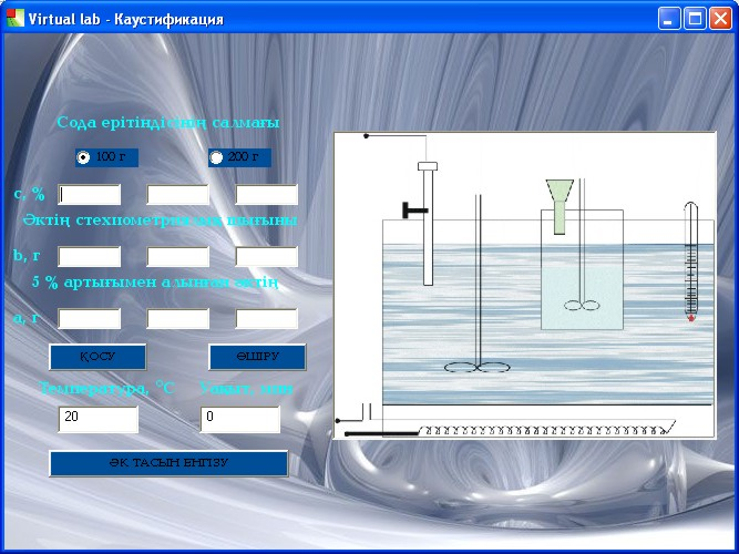
Then the student performs the cauterization process (Fig. 2. 2): selects the amount of soda solution given by the teacher (100 or 200 grams), and 3 different concentrations of the solution. If the concentration is entered correctly, then the stoichiometric coefficient of lime loss (b) and 5% excess (a) are calculated from equation (2.1)of the reaction (a)-and the data obtained are entered in the corresponding cells. If the concentrations are entered incorrectly or the values (b) and (a) are calculated incorrectly, clicking the "Add" button displays the errors that need to be corrected. You can only proceed to work if all the data is entered correctly.
To perform the work, use the instant process adjustment buttons "lime input", "power on", "temperature" and "timer". If the technological rules of the soda solution caustification process are violated, the mistakes made are also indicated. If the student makes more than three mistakes, they will be rated "unsatisfactory" and will start working again with the test resolution. If cauterization is performed correctly, the student proceeds to perform the suspension filtration processes (Fig.2.3) and washing the sludge (Fig. 2.4) using the" on" and" off " buttons. Then, the weights of the resulting filtrate, sludge, and wash water are indicated in the corresponding cells.2Based on the values of the total amount of NaOH and NA2CO33(calculated per NaOH) in the filtrate and sediment, the student calculates the degree of cauterization and enters its value in the corresponding cell. If the calculation is made correctly, the program builds a graph of the dependence of the degree of cauterization on the concentration of soda solution, and the student draws conclusions on the work.
|
|
|
Figure 2.2-1st stage of performing virtual laboratory work |
After successfully passing the test tasks, the student is given grades: for the answer 19-20 - "excellent", for the answer 17-18 - "good", for the answer 15-16 - "satisfactory". If the student answers less than 15 questions, the work is considered incomplete and must be repeated. When giving a student a grade for performing virtual work, mistakes made during the calculation of the degree of moxibustion, filtration, and moxibustion are taken into account.
-
Calculation of process performance indicators
The main indicator that characterizes the effectiveness of the process of obtaining caustic soda by chemical means is the degree of caustification. For its determination by formula (2.5), the weight of NaOH in the filtrate and sediment and the total weight of NaOH and NA2CO32CO3(calculated per NaOH) are calculated.
Example of calculating the degree of cauterization
Let us assume that titration of 10 ml of filtrate in the presence of a methyl solution took 25 ml (v1), and 10 ml of this filtrate-21 ml ерітіндісімен карбонатты тұндырғаннан кейін титрлеуге 21мл (v2) of a 1H HCI solution (K=0.95) after precipitation of carbonate with BASI2 solution. When calculating the concentrations of NaOH and NA2CO32CO3by formulas (2.11) and (2.12):
|
|

The amount of NaOH and NaCO3 in the total volume of filtrate obtained after cauterization (for example, the total volumeof filtrate V1=300 ml)3:
|
|


Wash water volume V2=200 ml. Titration of the 20 ml volume to determine its total alkalinity took 22 ml (v1) of 0.1 h HCI solution.΄) To determine the NaOH content in the wash water (sample volume 20 ml), it took 18 ml of a solution of 0.1 h H SI (v2) . When calculating the concentrations of NaOH and NA2CO32CO3by formulas (2.11) and (2.12):
|
|

Total amount of NaOH and NaCO3in the obtained wash water:
|
|


The total amount of NaOH obtained as a result of the cauterization process is 23.94+0.72=24.66 g. The amount of remaining soda is 6.04+0.21=6.25 g. or, based on NaOH, -6.25 x 80 / 106=4.72 g.
Degree of cauterization of soda solution (X):
|
|

Enters the results of analysis and calculation in Tables 2.1 and 2.2.
Table 2.1 Leachate analysis results
|
Primary solution |
Volume of 1H HCl solution, ml |
Filtrate analysis |
|||||||
|
Volume V, ml |
Composition Na2CO3-ң құрамы |
Volume V1, ml |
Composition Na2CO3-ң құрамы |
NaOHComposition of NaOH |
|||||
|
g/ l |
g |
v1 |
v2 |
g/ l |
g |
g/ l |
g |
||
|
|
|
|
|
|
|
|
|
|
|
Table 2.2 results of flushing water analysis
|
Сода ерітіндісіндегі NaNA2CO3 contentCOin soda solution, g / l |
Volume of 0.1 N HCl solution, ml |
Wash water analysis |
КKust-fikatsiydegree (X), % |
|||||
|
Volume V2, ml |
Composition Na2CO3-ң құрамы |
NaOHComposition of NaOH |
||||||
|
v1΄ |
v2΄ |
g/ l |
g |
g/ l |
g |
|||
|
|
|
|
|
|
|
|
|
|
:LABORATORY WORK#3
ELECTROCHEMICAL COPPER OF METALS
1. Purpose of the work:
1) experimental acquaintance with the processes of electrochemical (electroplating) coating of metals;
2) development of methods for calculating technological indicators of the process of electrochemical coating of metals.
3) determination of the influence of process parameters on the effectiveness of electrochemical mediation.
description of the installation and working procedure
3.1 installations, technical and instrumental means:
1. Installation of electrochemical coating of metals
2. laboratory scales VLTE-150
3. drying cabinet SHS-80
3.2 installation description
A schematic version of the electrochemical coating plant is shown in Figure 3.1. It consists of an electrolyzer (4), a voltmeter (7), a coulometer (3), and a rheostat (3) equipped with an anode (5) and a cathode (6). A glass container with a capacity of about 1 L is used as the electrolyzer. brass or copper plates that are firmly attached to the lid of the cell. A nickel-plated article or nickel-plated plate is used as the cathode.
|
|
|
1-direct current source; 2-rheostat; 3-coulometer; 4-electrolyzer; 5-anode; 6-cathode; 7-voltmeter; 8-ammeter; 9-eraser. Figure 3.1-schematic version of the laboratory installation for electrolysis |
3.3 procedure for performing work
1. preparation of the product for electrolysis.
Unevenness of the product surface, silt, rust, oil stains degrade the quality of the coating and the electrolysis process. Therefore, facing products must first be thoroughly cleaned. Iron cleans the surface of the product by mechanical and chemical methods. Mechanical methods use sandpaper or felt. Chrome or crocus pastes are used to polish the surface of products. To degrease the products and increase their water absorption capacity, they NaOH are treated with a hot alkaline NaOH solution with a concentration of 100 g / l or organic solutions (for example, ethanol).
2. the iron product is thoroughly washed with water before being placed in the electrolyzer, dried and weighed on a technical scale with an accuracy of 0.01 g.
3. For the Meditation process, a laboratory unit is assembled as shown in Figure 3.1. The cell is filled with the following electrolyte composition: CuSO45H2CuSO4 5H2O-250 g / l,2SO4 H2SO4-50 g/l. 3/4 of the length of the electrode plates should be immersed in the electrolyte.
4. the manufactured facing product is suspended in place of the cathode and immersed in the electrolyte. Turns on the electric current and sets the current supplied by the rheostat. Records current and voltage values based on instrument readings.
5. the electrolysis process is carried out within 5-10 minutes. After the copper process is completed, the electric current is turned off, the product is removed from the electrolyzer, dried and weighed on an analytical balance with an accuracy of 0.01 g.Determines the coating area of the product.
6. calculates the main indicators of the electrochemical process (output based on the average thickness of the metal coating and current).
Technological conditions of the process (duration of the process, current strength, average coating thickness, cathode coating area) may vary according to the teacher's task. By changing the process parameters, their influence on the electrochemical process parameters is determined and conclusions are drawn on the effectiveness of the process.
4 calculation of electrochemical process parameters
Calculation of metal coating thickness
The average degree of copper layer coverage қалыңдығын δort, (microns) is calculated by the formula:
δort
= (3.20)
where: Gcrown – difference of product weights before (G1) and after (G2) (Gcrown = G2 - G1), g; S-copper area of the product, cm2; - Density of facing metal (Cu= 8.95 g / cm3), g / cm3.
4.2 calculation of current consumption
The current output is calculated by formula (3.1), where Gcrown is the mass of copper deposited on the cathode, g; Gteor is the theoretical amount of copper required for deposition on the cathode under given conditions, g.the theoretical amount of metal deposited is calculated by formula (3.2) In accordance with Faraday's laws.
The obtained experimental data and calculation results are entered in Table 3.1.
Table 3.1-indicators of the electrochemical mediation process
|
Cathode weight, g |
Mass of copper deposited on the cathode Gcrown, g |
Current strength, but |
Immersion of the cathode in an electric field area, cm 22 |
Electric- liz time, h |
Coating δort, microns |
Current output ŋ, % |
|
|
For electrolysis up to G1 |
Electro G2 after Liz |
||||||
|
|
|
|
|
|
|
|
|
LABORATORY WORK #4
SOLID FUEL TECHNICAL ANALYSIS
1. Purpose of the work:
-
Introduction to standard methods for determining humidity, ash content, and volatiles in solid fuels.
2) determination of solid fuel quality.
3 description of the installation and working procedure
3.1 installations, technical and instrumental means:
1. drying cabinet SHS-80
2. muffle furnace SNOL 6,7/1300
3. Laboratory scales VLTE-150
4. Desiccator
3.2 method for determining the humidity of solid fuel
You can determine the fuel humidity by direct and indirect methods. When determining the fuel humidity by direct weight method анықтау кезінде (MST 9616-60), the fuel sample is dried in an inert gas stream (usually nitrogen) at 105-1100C, and the released water vapor is absorbed with magnesium chloride or sulfuric acid. When determining humidity by direct volumetric method анықтау кезінде (MST 9339-60), the fuel sample is heated with the addition of toluene, pumping the moisture contained in it together with toluene, and then condenses the water and measures the volume. These approaches produce very accurate results, but they are considered more complex than comparable approaches.
The indirect approach is used to determine the moisture content of brown and hard coals, anthracites and oil shales жанама тәсіл(GOST 6379-59). This approach is based on drying the fuel sample in a drying cabinet at 105-110°C to a constant mass . The loss of fuel weight as a result of drying is considered humidity.
Procedure for determining the humidity of solid fuel by indirect method:
1. coal is ground to a powdery state.
2. The weight is pre-weighed30 ммon an analytical balance with an accuracy of 0.01 g, placing 1 g of fuel in a glass container with a height of 20-30 mm, a diameter of 35-40 mm, weighed on the scale. The thickness of the fuel layer in the vessel should not exceed 5 mm.
3. The fuel particles are lightly shaken and smoothed and pre105-1100-dried in a drying cabinet heated to 105-110 0 C. When drying, the lid of the container must be partially opened. The drying time for brown coals is 90min; for anthracites-120min; and for Kalgan fuels-50-60min.
4. after the specified time, the fuel container is removed from the drying cabinet, the lid is completely closed and first left in the air for 2-3 minutes, then cooled to room temperature in a desiccator and weighed on an analytical balance with an accuracy of 0.001 g.
5. control dryingis carried out within 30 minutes at 105-110 0s. If the weight loss is more than 0.01 grams, then the drying is repeated until the weight reduction is less than 0.01 g or the weight gain begins as a result of coal oxidation. For calculation, in case of an increase in the weight of coal, take the value of the weight before it.
6. humidity of the test fuel W ( % ) is calculated by the formula:
|
W = |
(4.1) |
|
where: ΔG1-change in fuel weight after drying, g; Δg1G1=G-G1; G is the initial mass of the test fuel, g;G1is the massрof the test fuel, g. |
|

3.3 methodology for determining fuel ash content
To determine the ash content of solid fuel (MSST 6382-52), it is necessary to ignite a fuel sample and heat the resulting ash to a constant mass: anthracite, brown and hard coal - at 800±25°C, shale-at 850±25°C. The use of high temperatures in the analysis of shales is explained by the need for high temperatures for the decomposition of carbonates in their mineral part.
Procedure for determining the ash content of solid fuel:
1. previously, the mass is placed in a porcelain crucible with a height of 25-30 mm and a diameter of 30 mm, weighed on an analytical balance, a sample of 1 g of fuel is weighed on an analytical balance with an accuracy of 0.001 g±250and placed in a muffle furnace heated to 850±25 0 C.
2. the resulting ash residue is heated at this temperature for 1.5 hours. Then, using a clamp, the crucible is removed from the muffle furnace and cooled first in air for 5 minutes, and then on a desiccator to room temperature.
3. The weight of the cooled crucible is weighed on an analytical balance with an accuracy of 0.001 g.
4. For reliable results, the ash is heated every 30 minutes until the difference between the last two measured weightsгis less than 0.001 g. If the weight increases, then the value of the weight before it is used for calculation.
5. the ash content of fuel a (%) is calculated by the formula:
|
A= |
(4.2) |
|
where: G -initial mass of fuel, g; G2-mass of ash residue,g. |
|

6. to convert the ash content of fuel to absolute dry fuel (ab), the formula given below is used:
|
Aab
= |
(4.3) |

3.4 method of determination of volatile substances in solid fuel composition
The method for determining the consumption of volatile substances in coal (in accordance with GOST 6382-65) 850±is based on determining the lost mass of coal by heating a fuel sample in the interval of 7 minutes at 850±25°C.
Procedure for determining the content of volatile substances in solid fuels:
1. humidity (W) 1 gram of known fuel is placed in a porcelain crucible 40 mm high, 30 mm in diameter, pre-weighed by weight, салмағынand weighed on an analytical balance with an accuracy of ±0.0001 g.
2. Slightly closes the lid of the crucible. Volatiles escape through the holes in the lid.
3. The muffle furnace 800±is preheated to 800±25°C. The crucible is placed so that it stands at a height of 10-20 mm above the bottom of the electric furnace. Heat-resistant stands are used for this purpose. Thermal paste is used to measure the temperature. The hot side of the thermal paste should be 10-20 mm above the bottom of the oven.
4. After heating the coal for 7 minutes, the crucible with a closed surface is removed from the furnace using tongs and cooled in air for 3 to 5 minutes, and then on a desiccator to room temperature.
5. The weight of the cooled crucible is weighed on an analytical balance with an accuracy of 0.001 g. The content of volatile substances in the test fuel V ( % ) is calculated using the following formula:
|
Vab
= |
(4.4) |
|
where: G – initial mass of fuel, g; ΔG33 – change in fuel weight after heating, g; Δg3G3= G-G3; GG3 – Mass of fuel after heating, g; W – humidity content in the test fuel,%. |
|

6. draws conclusions about the fuel quality based on the data obtained (humidity, ash content of fuel, content of volatile substances).
LABORATORY WORK #5
DETERMINATION OF WATER QUALITY INDICATORS
1 Purpose of the work:
-
Practical introduction to standard methods for determining water hardness and oxidation.
2) determination of the quality of various waters.
3 methodology of work execution
3.1 installations, technical and instrumental means:
1.electric tile with your face covered
2. chemical cookware
3. Titration setting
4. Liston A 1210 aquadistillators
3.2 determination of carbonate hardness of water
1. using a measuring cylinder, measure 100 ml-n of the test water (from a water pipe or other water source) and pour it into a conical armor.
2. Add 2-3 drops of the methylmercury indicator to the water and titrate it with 0.1 N hydrochloric acid solution (V1) to a light pink color.
When hydrochloric acid reacts with calcium bicarbonates during titration, the following reaction occurs:
|
Ca(HCO3)2 + 2HCl = CaCl2 + 2H2O + 2CO2 ↑ |
(5.10) |
3. The carbonate hardness of water Nk (mg-eq) is calculated by the formula:
|
|
(5.11) |
|
where: V1 is the volume of hydrochloric acid 0.1 n, ml; 0.0028,is the titer of hydrochloric acid for calcium oxide; 10000 is the conversion coefficient; 20.04 is the conversion coefficient of the obtained data for hardness mg-eq. |
|

3.3 determination of total and non-carbonate water hardness
1. after determining the carbonate hardness, the test water is boiled in the interval of 5-10 minutes until the carbon dioxide disappears.
2. using a dropper, add 25 ml of the mixed mixture (NA2CO32CO3+NaOH) and boil again in an interval of 5-10 minutes until the precipitation of calcium and magnesium salts, after which the following reactions occur:
|
CaCl2 + Na2CO3= CaCO3 + 2NaCl |
(5.12) |
|
MgCl2 + 2NaOH = Mg(OH)2 + 2NaCl |
(5.13) |
|
Mg SO4 + 2NaOH = Mg(OH)2 + Na2SO4 |
(5.14) |
|
|
|
3. then the solution is cooled and transferred together with the sediment to a 250 ml volumetric flask and diluted with distilled water to the set mark.
4. the sediment is filtered. The filtrate volume of 100 ml is poured into a conical flask using a dropper.
5. add 2-3 drops of the methylmercury indicator to the sample and titrate with a 0.1 n (V2) hydrochloric acid) solution until the color changes to a faint pink.
6. in another cone flaskараласпа қоспаның , pour a volume of 25 ml of an immiscible mixture (2CO3NA2CO3+NaOH) and titrate with a solution of 0.1 h hydrochloric acid (V3) until the color changes to a faint pink with the addition of the indicator methylmercury 2-3.
7. To calculate the total stiffness (NWж), the formula is used:
|
Hw = (V3-2,5V2) x1, 4 |
(5.15) |
|
where: v3is thevolume of 25 ml of the mixed mixture (NA2CO32CO3+NaOH) 25мл көлемін титрлеуге кеткенvolume of 0.1 n hydrochloric acid used for titration, ml; V2-volume of water under study volume of 0.1 n hydrochloric acid used for titration, ml; 2.5-dilution ratio. |
|
8. Non-carbonate hardness (n. k. e.) is calculated from the difference between total and carbonate hardness:
|
Nk. e. = Nw - Nk (5.16) |
3.4 determination of water oxidation
The data obtained in determining the oxidation of water allow us to assume the amount of oxygen required for the oxidation of organic impurities contained in water. To determine the oxidation of water:
1. the volume of test water of 100 ml is poured into a conical flask using a measuring cylinder.
2. add 5 ml of a solution of sulfuric acid (1:3) and 10 ml of a solution of potassium permanganate (A) 0.01 n to the water sample. 10мл-н қосады.
3. the solution is boiled for 10 minutes. At the end of boiling0,01н , 10 ml of 0.01 N oxalic acid solution (C) is added to the hot solution) and the excess 0.01 n potassium permanganate solution (B) is titrated to a weak pink color.
4. to calculate the oxidation of water X (oxygen content in 1 liter of water, mg/l), the formula is used:
|
X=((A+B)-C)х0,08х10 |
(5.17) |
|
where: a - volume of 0.01 N KMnO4 solution filled with water for the oxidation of organic impurities4, ml; B–volume of 0.01 n KMnO4 solution used for titration4, ml; C-volume of 0.01 n oxalic acid solution (2С2О4H2S2O4), ml; 0.08-KMnO44 - content oxygen content corresponding to the volume of 1 ml of a solution of 0.01 n, ml; 10 is the coefficient of calculation of the obtained data per unit mg/l. |
|
LABORATORY WORK #6
ANNEALING PROCESS OF SULFUR PYRITE
learning
1 Purpose of the work:
1) experimental study of the heterogeneous process that occurs during the combustion of sulfur pyrite.
2) determination of the influence of temperature, the degree of grinding of pyrites and the duration of the process on the SO2 output2(the degree of sulfur combustion) and mastering the methods of process control.
3) determination of the effective technological rule of the process.
3 description of the installation and working procedure
3.1 installations, technical and instrumental means:
1. laboratory tube electric furnace SNOL 0,2 / 1250
2. chemical cookware
3. Titration setting
4. Liston A 1210 aquadistillators
5. laboratory scales VLTE-150
6. drainage pump
3.2 installation description
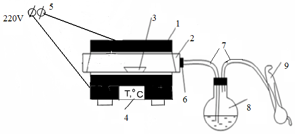
A schematic version of the pyrite kiln is shown in Fig. 6. 1. The unit consists of a tubular electric furnace (1) with a quartz tube (2). A boat (3) with pyrite is placed inside the quartz tube. To control and regulate the temperature inside the furnace, the furnace is equipped with an automatic control system. The temperature in the reaction zone is displayed on the display (4)at the bottom of the furnace. One side of the quartz tube is open, and the other side is attached by a rubber stopper (6) connected to the glass tube (7). Through the glass tube (7), the gas generated by the process is directed to the absorption flask (8). A drainage pump (9) is used to absorb gas from the furnace into the absorption flask.
|
|
|
1-electric oven, 2-quartz tube; 3-boat; 4 – temperature indicator; 5-direct current source; 6-rubber tube; 7-glass tubes, 8-absorption flask, 9-water pump. Figure 6.1-schematic version of the pyrite roasting plant. |
3.3 procedure for performing work
1. Pre-pour 100 ml of 0.1 N iodine solution into the absorption flask.
2. Before performing work, check that the installation is assembled correctly. The furnace tube is securely fixed by a rubber stopper connected to the glass tube.
3. then connects the oven to a power source.
4.0, 4 grams of Pyrite are weighed on an analytical scale with an accuracy of 0.001 g and placed in a boat.
5. when the furnace temperature reaches 500°C, the boat is placed inside the quartz tube by means of a clamp and the chute extraction is turned on. The annealing process is carried out for 60 minutes.
6. The gas coming out of the furnace is absorbed by a 0.1 n iodine solution in an absorption flask. If the iodine solution is completely discolored during the process, then an additional 25 ml of 0.1 n iodine solution must be poured into the glass container.
As a result of absorption, iodine reacts with sulfur dioxide:
|
SO2+2H2O+J2=H2SO4+2HJ |
(6.6) |
|
|
|
7. after the process time has elapsed, the furnace is disconnected from the current source and the boat is removed from the inside of the quartz tube using a clamp.
9. starch is added to the solution inside the glass container as an indicator and titrated with 0.1 n sodium thiosulfate solution until the solution discolors. During the titration process, the following reaction occurs:
|
J2+2 Na2S2O3 = 2 NaJ+Na2S4O6 |
(6.7) |
|
|
|
9. calculates the mass of burned sulfur by the volume spent on titration of the solution.
4 calculation of technological indicators of the process
1. knowing the sulfur content in pyriteSO2-ң , we can calculate the theoretical amount of SO2 (gteor) released during complete combustion of sulfur:
|
Gтеорtheory= |
(6.7) |
|
where: a is the mass of pyrite, g; b is the sulfur content in Pyrite,%; 32 and 64 arethe molecular weights of S and SO2, respectively. |
|

The calculation is performed according to the reaction equation (6.4).
2. Experimentally, the following formula is used to calculate the weight of burnt sulfur qS (g):
|
|
(6.9) |
|
|
|
|
where: 0.0016-titer of iodine
for sulfur, the content of sulfur in accordance with 1 ml of 0.1 n
iodine solution;
|
|


3. the amount of sulfur dioxide produced Gcrown (g) :
|
Gcrown = |
(6.10) |

4. degree of sulfur burning α (%):
|
|
(6.11) |

5. Күкіртті газдың шыны ыдыс
арқылы өткен уақытын белгілеп  =f(
=f( )
кинетикалық қисығын салуға қажет мәліметтерді
алады. Оқытушының тапсырмасы
бойынша күкірттің жану дәрежесінің
температураға немесе колчеданның майдалану дәрежесіне тәуелділігін
зерттеуге болады. Алынған мәліметтерді
6.1-ші кестеге енгізеді. Тағайындалған мәліметтер бойынша
күкіртқұрамдас шикізаттарды күйдіру процесінің тиімді ережесін
анықтауға болады.
)
кинетикалық қисығын салуға қажет мәліметтерді
алады. Оқытушының тапсырмасы
бойынша күкірттің жану дәрежесінің
температураға немесе колчеданның майдалану дәрежесіне тәуелділігін
зерттеуге болады. Алынған мәліметтерді
6.1-ші кестеге енгізеді. Тағайындалған мәліметтер бойынша
күкіртқұрамдас шикізаттарды күйдіру процесінің тиімді ережесін
анықтауға болады.
6.1 кесте - Колчеданды күйдіру процесінің көрсеткіштері
|
Тәжірибе№ |
Колчедан ның салма ғы а, г |
Колче- дандағы күкірт-тің құрамы b, % |
Күйді ру темпе-ратура- сы, 0С |
Күй-діру уақы- ты |
Nа2S2O3 ерітінді-сінің
мөлшері |
Жан-ған күкірт-тің мөлше-рі qS, г |
SO2-ң тәжі-рибе-лік мөлше-рі Gтәж, г |
SO2-ң теория лық мөлше-рі Gтеор, г |
Күкірт-тің жану дәреже- сі α, % |
|
|
|
|
|
|
|
|
|
|
|

 Жүктеу


 Жүктеу
шағым қалдыра аласыз

 Бұл курс Қазақстан Республикасы Оқу-ағарту министрлігімен келісілген